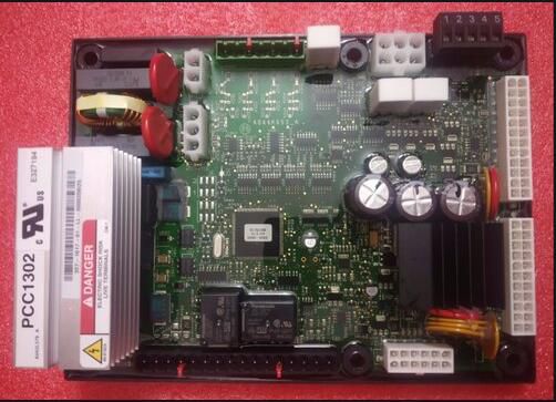
Cummins PCC1302 Generator Fault Code 118 Repair
Chinaobd2 is a leading supplier of all kinds of
Car Diagnostic Tool,
Truck Diagnostic Tool,
OBD2 Code Reader,
Car Key Programmer,
ECU Chip Tunning,etc. Currently, the top selling product including:
VCDS VAG COM Cable,
iProg+ Programmer,
Scania VCI3

This post show you guide on how to repair Cummins PCC1302 generator fault code 118 related trouble.
 Code 118 − Fuel Pressure OOR High (Warning)
Logic:Fuel pressure sensor signal is out of range – shorted high.
Possible Causes:
- Faulty fuel pressure sensor connections
- Faulty fuel pressure sensor
- Faulty engine harness
- Faulty extension harness
- Verify the calibrations in the ECM and the PowerCommand controls
Diagnosis and Repair:
- Faulty fuel pressure sensor connections
- Inspect the fuel pressure sensor and the engine harness connector pins.
- Disconnect the engine harness connector from the fuel pressure sensor.
- Inspect for corroded pins, bent or broken pins, pushed back or expanded pins.
- Inspect for evidence of moisture in or on the connector.
- Inspect for missing or damaged connector seals.
- Inspect for dirt or debris in or on the connector pins.
- Faulty fuel pressure sensor
- Active Sensor.
- Check the fuel pressure sensor supply voltage.
- Disconnect the engine harness connector from the fuel pressure sensor.
- Install the pressure sensor breakout cable between the sensor and thesensor harness connector.
- Measure the supply voltage by connecting the breakout cable’s supply andreturn connectors to the multimeter. If the reading is between 4.75 and 5.25VDC, then the supply voltage is correct.
- Check the fuel pressure sensor signal (sense) voltage.
- Disconnect the engine harness connector from the fuel pressure sensor
- Install the pressure sensor breakout cable between the sensor and thesensor harness connector.
- Measure the signal voltage by connecting the breakout cable’s signal andreturn connectors to the multimeter. If the reading is between 0.46 and 4.56V, then the signal voltage is correct. If not, sensor is faulty.
- Faulty engine harness
- Inspect the engine harness and the connector pins.
a> Disconnect the engine harness connector from the extension harness.
b>. Inspect for corroded pins, bent or broken pins, pushed back or expanded pins.
c> Inspect for evidence of moisture in or on the connector.
d> Inspect for missing or damaged connector seals.
e> Inspect for dirt or debris in or on the connector pin.
- Check for a short circuit from pin to pin.
a> Disconnect the engine harness from the extension harness.
b> Disconnect the engine harness connector from the fuel pressure sensor.
c> Disconnect the engine harness from all sensors that have a shared supply or
return with the fuel pressure sensor.
d> Measure the resistance from the fuel pressure 5 VDC supply pin on the engine
harness inline connector to all other pins in the engine harness inline connector.
e> Measure the resistance from the fuel pressure return pin on the engine harness
inline connector to all other pins in the engine harness inline connector.
f> Measure the resistance from the fuel pressure signal pin on the engine harness
inline connector to all other pins in the engine harness inline connector.
g> If all measurements are greater than 100k ohms, then the resistance is correct.
- Check for an open circuit.
a> Disconnect the engine harness from the extension harness.
b> Disconnect the engine harness connector from the fuel pressure sensor.
c> Measure the resistance from the fuel pressure return pin on the engine harness inline connector to the fuel pressure return pin on the engine harness sensor connector.
d> If the measurement is less than 10 ohms, then the resistance is correct.
- Faulty extension harness
- Inspect the extension harness and the control connector pins.
a> Disconnect the extension harness connector from the control.
b> Inspect for corroded pins, bent or broken pins, pushed back or expanded pins.
c> Inspect for evidence of moisture in or on the connector.
d> Inspect for missing or damaged connector seals.
e> Inspect for dirt or debris in or on the connector pins.
- Check for an open circuit.
a> Disconnect the extension harness connector from the control.
b> Disconnect the extension harness from the engine harness.
c> Measure the resistance from the fuel pressure return pin on the extension harness connector to the fuel pressure return pin on the extension harness inline connection.
d> If the measurement is less than 10 ohms, then the resistance is correct.
- Check for a short circuit from pin to pin.
a> Disconnect the extension harness connector from the control.
b> Disconnect the extension harness from the engine harness.
c> Measure the resistance from the fuel pressure 5 VDC supply pin on the extension harness connector to all other pins in the extension harness connector.
d> Measure the resistance from the fuel pressure return pin on the extension
harness connector to all other pins in the extension harness connector.
e> Measure the resistance from the fuel pressure signal pin on the extension
harness connector to all other pins in the extension harness connector.
f> If all measurements are greater than 100k ohms, then the resistance is correct.
- Verify the calibrations in the ECM and the PowerCommand controls
- Using the display or the InPower Service tool, verify the calibration in the PCC.
a> If the calibration in the PCC matches the latest calibration on the InCal website, then the calibration is correct. If it does not, update the calibration to the latest.
b> Using the InSite Service tool, verify the calibration in the ECM.
- If the calibration in the ECM matches the latest calibration on QSOL, then thecalibration is correct. If it does not, update the ECM to the latest calibration.
This article tech Supported by
China OBD2,